
PART COLIBRI 21CC - Brush cutter PARTNER - Free user manual and instructions
Find the device manual for free PART COLIBRI 21CC PARTNER in PDF.

User questions about PART COLIBRI 21CC PARTNER
0 question about this device. Answer the ones you know or ask your own.
Ask a new question about this device
Download the instructions for your Brush cutter in PDF format for free! Find your manual PART COLIBRI 21CC - PARTNER and take your electronic device back in hand. On this page are published all the documents necessary for the use of your device. PART COLIBRI 21CC by PARTNER.
USER MANUAL PART COLIBRI 21CC PARTNER
natural_image
Technical line drawing of a mechanical device with lever and handle (no text or symbols)GB
INSTRUCTION MANUAL
IMPORTANT INFORMATION: Please read these instructions carefully and make sure you understand them before using this unit. Retain these instructions for future reference.
FR
MANUEL D'INSTRUCTIONS
text_image
Fuel tank ON/OFF Switch Choke Starter Handle Primer Bulb Throttle Assist handle adjustment Assist handle Tube Shield Trimmer head Wrench ManualIDENTIFICATION OF SYMBOLS
A

D

G
1
B

E

[Non-Text]

J

c

F
H
K
A. WARNING! This trimmer can be dangerous! Careless or improper use can cause serious or even fatal injury.
B. Read and understand the instruction manual before using the trimmer.
C. Never use blades with this tool.
D. WARNING! The trimmer line can throw objects violently. You can be blinded or injured. Always wear eye protection.
E. Always use:
Ear protection
Protective glasses or visor
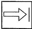
F. Assist handle to be positioned only below the arrow.
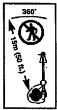
G. The operator of the machine must insure that no one comes within a 15 meter radius while working. When several operators are working within the same area a safety distance of at least 15 meters must be observed.
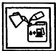
H. Use unleaded or quality leaded petrol and two-stroke oil mixed at a ratio of 2.5%.
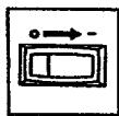
I. Engine ON/OFF Switch.
J. Sound power level
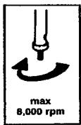
K. Max speed of output axle, rpm
SAFETY RULES
WARNING: When using gardening appliances, basic safety precautions should always be followed to reduce the risk of fire and serious injury. Read and follow all instructions. This power unit can be dangerous! Operator is responsible for following instructions and warnings on unit and in manual. Read entire instruction manual before using unit! Be thoroughly familiar with the controls and the proper use of the unit. Restrict the use of this unit to persons who read, understand, and follow instructions and warnings on unit and in manual. Never allow children to operate this unit.

INSTRUCTION
MANUAL

SAFETY INFORMATION
ON THE UNIT
DANGER: Never use blades, wire, or flailing devices. This unit is designed for line trimmer use only. Use of any other accessories or attachments will increase the risk of injury.


WARNING: Trimmer line throws objects violently. You and others can be blinded/injured. Wear safety glasses and leg protection. Keep body parts clear of rotating line. Safety Glasses or similar eye protection

flowchart
graph TD
    A["Boots"] --> B["Hazard Zone"]
    B --> C["15 meters"]
    C --> D["Distance measurement"]
    style A fill:#f9f,stroke:#333
    style B fill:#ccf,stroke:#333
    style C fill:#cfc,stroke:#333
    style D fill:#fcc,stroke:#333
Keep children, bystanders, and animals 15 meters away. If approached stop unit immediately. If situations occur which are not covered in this manual, use care and good judgement. If you need assistance, contact your authorized service dealer.
OPERATOR SAFETY
- Dress properly. Always wear safety glasses or similar eye protection when operating, or performing maintenance, on your unit (safety glasses are available). Eye protection should be marked Z87.
-
Always wear face or dust mask if operation is dusty.
• Always wear heavy, long pants, long sleeves, boots, and gloves. Wearing safety leg guards is recommended. -
Always wear foot protection. Do not go barefoot or wear sandals. Stay clear of spinning line.
- Secure hair above shoulder length. Secure or remove loose clothing or clothing with loosely hanging ties, straps, tassels, etc. They can be caught in moving parts.
- Being fully covered also helps protect you from debris and pieces of toxic plants thrown by spinning line.
- Stay Alert. Do not operate this unit when you are tired, ill, upset or under the influence of alcohol, drugs, or medication. Watch what you are doing; use common sense.
- Wear hearing protection.
- Never start or run inside a closed room or building. Breathing exhaust fumes can kill.
- Keep handles free of oil and fuel.
UNIT / MAINTENANCE SAFETY
- Disconnect the spark plug before performing maintenance except carburetor adjustments.
- Look for and replace damaged or loose parts before each use. Look for and repair fuel leaks before use. Keep in good working condition.
- Replace trimmer head parts that are chipped, cracked, broken, or damaged in any other way before using the unit.
- Maintain unit according to recommended procedures. Keep cutting line at proper length.
- Use only 2 mm diameter Partner® brand line. Never use wire, rope, string, etc.
- Install required shield properly before using the unit. Use only specified trimmer head; make sure it is properly installed and securely fastened.
- Make sure unit is assembled correctly as shown in this manual.
- Make carburetor adjustments with lower end supported to prevent line from contacting any object.
- Keep others away when making carburetor adjustments.
- Use only recommended Partner® accessories and replacement parts.
- Have all maintenance and service not explained in this manual performed by an authorized service dealer.
FUEL SAFETY
- Mix and pour fuel outdoors.
- Keep away from sparks or flames.
- Use a container approved for fuel.
- Do not smoke or allow smoking near fuel or the unit.
- Avoid spilling fuel or oil. Wipe up all fuel spills.
- Move at least 3 meters away from fueling site before starting engine.
- Stop engine and allow to cool before removing fuel cap.
• Always store gasoline in a container approved for flammable liquids.
CUTTING SAFETY
WARNING: Inspect the area before each use. Remove objects (rocks, broken glass, nails, wire, etc.) which can be thrown by or become entangled in line. Hard objects can damage the trimmer head and be thrown causing serious injury.
- Use only for trimming, scalping, mowing and sweeping. Do not use for edging, pruning or hedge trimming.
- Keep firm footing and balance. Do not overreach.
- Keep all parts of your body away from muffler and spinning line. Keep engine below waist level. A hot muffler can cause serious burns.
- Cut from your right to your left. Cutting on left side of the shield will throw debris away from the operator.
- Use only in daylight or good artificial light.
- Use only for jobs explained in this manual.
- Allow the engine to cool; secure unit before storing or transporting in vehicle.
- Empty fuel tank before storing or transporting the unit. Use up fuel left in the carburetor by starting engine and letting it run until it stops.
TRANSPORTING AND STORAGE
- Store unit and fuel in an area where fuel vapors cannot reach sparks or open flames from water heaters, electric motors or switches, furnaces, etc.
- Store unit so line limiter cannot accidentally cause injury. Unit can be hung by the tube.
- Store the unit out of the reach of children
SPECIAL NOTICE: Exposure to vibrations through prolonged use of gasoline powered hand tools could cause blood vessel or nerve damage in the fingers, hands, and joints of people prone to circulation disorders or abnormal swellings. Prolonged use in cold weather has been linked to blood vessel damage in otherwise healthy people. If symptoms occur such as numbness, pain, loss of strength, change in skin color or texture, or loss of feeling in the fingers, hands, or joints, discontinue the use of this tool and seek medical attention. An anti-vibration system does not guarantee the avoidance of these problems. Users who operate power tools on a continual and regular basis must monitor closely their physical condition and the condition of this tool.
ASSEMBLY
WARNING: Make sure unit is properly assembled and all fasteners are secure. Examine parts for damage. Do not use damaged parts.
It is normal for the fuel filter to rattle in the empty fuel tank.
Finding fuel or oil residue on muffler is normal due to carburetor adjustments and testing done by the manufacturer.
ADJUSTING THE HANDLE
WARNING: When adjusting the handle, be sure it remains between the trigger and the safety label. Assist handle must be positioned only below the arrow.
- Loosen wing nut on handle.
- Rotate the handle on the tube to an upright position; retighten wing nut.
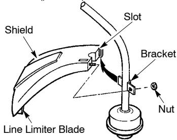
ATTACHING THE SHIELD
WARNING: The shield must be properly installed. The shield provides partial protection from the risk of thrown objects to the operator and others and is equipped with a line limiter which cuts excess line. The line limiter (on underside of shield) is sharp and can cut you.
- Remove nut from shield.
- Insert bracket into slot on shield.
- Pivot shield until bolt passes through hole in bracket.
- Reinstall nut and tighten securely with wrench (provided).
text_image
Shield Slot Bracket Nut Line Limiter BladeOPERATION
WARNING: Be sure to read the fuel information in the safety rules before you begin. If you do not understand the safety rules, do not attempt to fuel your unit. Contact an authorized service dealer.
FUELING ENGINE
WARNING: Remove fuel cap slowly when refueling.
This engine is certified to operate on unleaded gasoline. Before operation, gasoline must be mixed with a good quality 2-cycle air-cooled engine oil. We recommend Partner® brand oil mixed at a ratio of 40:1 (2.5%). A 40:1 ratio is obtained by mixing 5 liters of unleaded gasoline with 0,125 liter of oil. DO NOT USE automotive oil or boat oil. These oils will cause engine damage. When mixing fuel, follow instructions printed on oil container. Once oil is added to gasoline, shake container momentarily to assure that the fuel is thoroughly mixed. Always read and follow the safety rules relating to fuel before fueling your unit.
IMPORTANT
Experience indicates that alcohol blended fuels (called gasohol or using ethanol or methanol) can attract moisture which leads to separation and formation of acids during storage. Acidic gas can damage the fuel system of an engine while in storage. To avoid engine problems, empty the fuel system before storage for 30 days or longer. Drain the gas tank, start the engine and let it run until the fuel lines and carburetor are empty. Use fresh fuel next season. Never use engine or carburetor cleaner products in the fuel tank or permanent damage may occur.
HOW TO STOP YOUR UNIT
- To stop the engine, move the ON/OFF switch to the OFF position.
HOW TO START YOUR UNIT
WARNING: The trimmer head will turn while starting the engine. Avoid any contact with the muffler. A hot muffler can cause serious burns.
STARTING A COLD ENGINE (or a warm engine after running out of fuel)
Starting Position
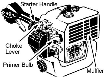
text_image
Starter Handle Choke Lever Primer Bulb Muffler- Set unit on a flat surface.
- Move ON/OFF switch to the ON position.
- Slowly press the primer bulb 6 times
- Move choke lever to FULL CHOKE position.
- Squeeze and hold trigger through all remaining steps.
- Pull starter rope handle sharply until engine sounds as if it is trying to start, but do not pull rope more than 6 times.
- As soon as engine sounds as if it is trying to start, move choke lever to HALF CHOKE.
- Pull starter rope sharply until engine runs, but no more than 6 pulls. If the engine doesn't start after 6 pulls (at the HALF CHOKE position), move the choke lever to the FULL CHOKE position and press the primer bulb 6 times. Squeeze and hold the throttle trigger and pull the starter rope 2 more times. Move the choke lever to the HALF CHOKE position and pull the starter rope until the engine runs, but no more than 6 pulls.
NOTE: If engine still doesn't start, it is probably flooded. Proceed to STARTING A FLOODED ENGINE. - Once the engine starts, allow it to run 10 seconds, then move the choke lever to OFF CHOKE. Allow the unit to run for 30 more seconds at OFF CHOKE before releasing the throttle trigger.
NOTE: If engine dies with the choke lever in the OFF CHOKE position, move the choke lever to the HALF CHOKE position and pull the rope until engine runs, but no more than 6 pulls. - Move ON/OFF switch to the ON position.
- Move the choke lever to the HALF CHOKE position.
- Squeeze and hold the throttle trigger. Keep throttle trigger fully squeezed until the engine runs smoothly.
- Pull starter rope sharply until engine runs, but no more than 5 pulls.
- Allow engine to run 15 seconds, then move the choke lever to the OFF CHOKE position.
STARTING A WARM ENGINE
NOTE: If engine has not started, pull starter rope 5 more pulls. If engine still does not run, it is probably flooded.
STARTING A FLOODED ENGINE
Flooded engines can be started by placing the choke lever in the OFF CHOKE position; then, pull the rope to clear the engine of excess fuel. This could require pulling the starter handle many times depending on how badly the unit is flooded.
If the unit still doesn't start, refer to TROUBLESHOOTING TABLE.
Cut from your right to your left.

WARNING: Always wear eye protec-
tion and hearing protection. Never lean over the trimmer head. Rocks or debris can ricochet or be thrown into eyes and face and cause blindness or other serious injury.
Do not run the engine at a higher speed than necessary. The cutting line will cut efficiently when the engine is run at less than full throttle. At lower speeds, there is less engine noise and vibration. The cutting line will last longer and will be less likely to "weld" onto the spool.
Always release the throttle trigger and allow the engine to return to idle speed when not cutting. To stop engine:
- Release the throttle trigger.
- Move the ON/OFF switch to the OFF position.
Advance line by tapping the bottom of the cutting head lightly on the ground while engine is running at full speed. The metal line limiter blade attached to the guard will cut the line to the proper length.

WARNING: Use only 2 mm diameter
line. Other sizes and shapes of line will not advance properly and will result in improper cutting head function or can cause serious injury. Do not use other materials such as wire, string, rope, etc. Wire can break off during cutting and become a dangerous missile that can cause serious injury.
CUTTING METHODS

WARNING: Use minimum speed and not crowd the line when cutting around d objects (rock, gravel, fence posts, etc.), which can damage the trimmer head, become angled in the line, or be thrown causing a porous hazard.
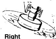
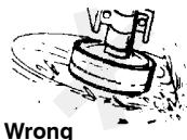
- The tip of the line does the cutting. You will achieve the best performance and minimum line wear by not crowding the line into the cutting area. The right and wrong ways are shown below.
Tip of the Line
Does The Cutting
Line Crowded Into
Work Area
- The line will easily remove grass and weeds from around walls, fences, trees and flower beds, but it also can cut the tender bark of trees or shrubs and scar fences.
- For trimming or scalping, use less than full throttle to increase line life and decrease head wear, especially:
• During light duty cutting.
- Near objects around which the line can-wrap such as small posts, trees or fence wire.
- For mowing or sweeping, use full throttle for a good clean job.
TRIMMING - Hold the bottom of the trimmer head about 80 mm above the ground and at an angle. Allow only the tip of the line to make contact. Do not force trimmer line into work area.
Trimming

text_image
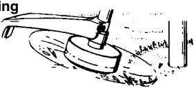
Trimming 3 in. (8 cm) Above GroundSCALPING - The scalping technique removes unwanted vegetation. Hold the bottom of the trimmer head about 80 mm above the ground and at an angle. Allow the tip of the line to strike the ground around trees, posts, monuments, etc. This technique increases line wear.
Scalpi
natural_image
Diagram of a hammer striking a circular object with a base, no text or symbols presentMOWING - Your trimmer is ideal for mowing in places conventional lawn mowers cannot reach. In the mowing position, keep the line parallel to the ground. Avoid pressing the head into the ground as this can scalp the ground and damage the tool.
Mowing

natural_image
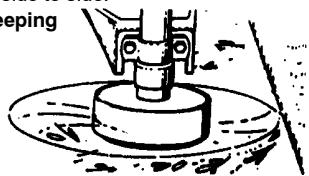
Simple line drawing of a mechanical device with a base and lever, no text or symbols presentSWEEPING - The fanning action of the rotating line can be used for a quick and easy clean up. Keep the line parallel to and above the surfaces being swept and move the tool from side to side.
Sweeping
natural_image
Illustration of a mechanical device with a rotating base and clamped components (no text or symbols)MAINTENANCE

WARNING: Disconnect the spark g before performing maintenance except carburetor adjustments.
CHECK FOR LOOSE
FASTENERS AND PARTS
- Spark Plug Boot
- Air Filter
- Housing Screws
- Assist Handle Screw
- Debris Shield
CHECK FOR DAMAGED OR WORN PARTS
Contact an authorized service dealer for replacement of damaged or worn parts.
- ON/OFF Switch - Ensure ON/OFF switch functions properly by moving the switch to the OFF position. Make sure engine stops; then restart engine and continue.
- Fuel Tank - Discontinue use of unit if fuel tank shows signs of damage or leaks.
- Debris Shield - Discontinue use of unit if debris shield is damaged.
INSPECT AND CLEAN UNIT AND LABELS
- After each use, inspect complete unit for loose or damaged parts. Clean the unit and labels using a damp cloth with a mild detergent.
- Wipe off unit with a clean dry cloth.
CLEAN AIR FILTER
A dirty air filter decreases engine performance and increases fuel consumption and harmful emissions. Always clean after every 5 hours of operation.
- Clean the cover and the area around it to keep dirt from falling into the carburetor chamber when the cover is removed.
- Remove parts as illustrated.
NOTE: Do not clean filter in gasoline or other flammable solvent to avoid creating a fire hazard or producing harmful evaporative emissions.
- Wash the filter in soap and water.
- Allow filter to dry.
- Add a few drops of oil to the filter; squeeze the filter to distribute oil.
- Replace parts.
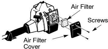
text_image
Air Filter Screws Air Filter CoverREPLACE SPARK PLUG
Replace the spark plug each year to ensure the engine starts easier and runs better. Set spark plug gap at 0,6 mm. Ignition timing is fixed and nonadjustable.
- Twist, then pull off spark plug boot.
- Remove spark plug from cylinder and discard.
- Replace with Champion RCJ-6Y spark plug and tighten securely with a 19 mm socket wrench.
- Reinstall the spark plug boot.
SERVICE AND ADJUSTMENTS
REPLACING THE LINE
- Move the ON/OFF switch to the OFF position.
- Disconnect the spark plug lead wire.
- Remove spool by firmly pulling on tap button. Clean entire surface of hub and spool. Replace with a pre-wound spool, or cut a length of 6 meters of 2 mm diameter Partner® brand line.
WARNING: Never use wire, rope, string, etc., which can break off and become a dangerous missile.
4. Insert one end of the line about 1 cm into the small hole on the inside of spool.
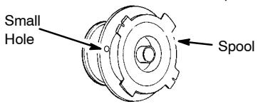
text_image
Small Hole Spool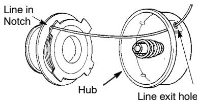
text_image
Line in Notch Hub Line exit hole- Wind the line evenly and tightly onto the spool. Wind in the direction of the arrow found on the spool.
- Push the line into the notch, leaving 7 - 12 cm unwound.
- Insert the line into the exit hole in the hub as shown in the illustration.
- Align the notch with the line exit hole.
-
Push spool into hub until it snaps into place.
-
Pull the line extending outside of the hub to release it from the notch.
CARBURETOR ADJUSTMENT
WARNING: Keep others away when making idle speed adjustments. The trimmer head will be spinning during this procedure. Wear your protective equipment and observe all safety precautions.
The carburetor has been carefully set at the factory. Adjustments may be necessary if you notice any of the following conditions:
- Engine will not idle when the throttle is released.
Make adjustments with the unit supported so the cutting attachment is off the ground and will not make contact with any object. Hold the unit by hand while running and making adjustments. Keep all parts of your body away from the cutting attachment and muffler.
Idle Speed Adjustment
Allow engine to idle. Adjust speed until engine runs without stalling (idle speed too slow).
- Turn idle speed screw clockwise to increase engine speed if engine stalls or dies.
- Turn idle speed screw counterclockwise to decrease engine speed.
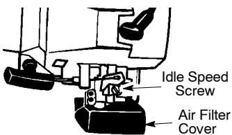
text_image
Idle Speed Screw Air Filter CoverIf you require further assistance or are unsure about performing this procedure, contact an authorized service dealer.
STORAGE
WARNING: Perform the following steps after each use:
- Allow engine to cool before storing or transporting.
- Store unit and fuel in a well ventilated area where fuel vapors cannot reach sparks or open flames from water heaters, electric motors or switches, furnaces, etc.
- Empty fuel tank before storing or transporting the unit.
- Store unit and fuel well out of the reach of children.
- Store unit with all guards in place. Position unit so that any sharp object cannot accidentally cause injury.
SEASONAL STORAGE
Prepare unit for storage at end of season or if it will not be used for 30 days or more.
If your unit is to be stored for a period of time:
- Clean the entire unit before lengthy storage.
- Store in a clean dry area.
- Lightly oil external metal surfaces.
ENGINE
- Remove spark plug and pour 1 teaspoon of 40:1, 2-cycle engine oil (air cooled) through the spark plug opening. Slowly pull the starter rope 8 to 10 times to distribute oil.
- Replace spark plug with new one of recommended type and heat range.
-
Clean air filter.
-
Check entire unit for loose screws, nuts, and bolts. Replace any damaged, broken, or worn parts.
- At the beginning of the next season, use only fresh fuel having the proper gasoline to oil ratio.
OTHER
- Do not store gasoline from one season to another.
- Replace your gasoline can if it starts to rust.
TROUBLESHOOTING TABLE
WARNING: Always stop unit and disconnect spark plug before performing all of the recommended remedies below except remedies that require operation of the unit.
| TROUBLE | CAUSE | REMEDY |
| Engine will not start. | 1. ON/OFF switch in OFF position.2. Engine flooded.3. Fuel tank empty.4. Spark plug not firing.5. Fuel not reaching carburetor.6. Carburetor requires adjustment. | 1. Move ON/OFF switch to ON position.2. See “Starting a Flooded Engine” in Operation Section.3. Fill tank with correct fuel mixture.4. Install new spark plug.5. Check for dirty fuel filter; replace. Check for kinked or split fuel line; repair or replace.6. Contact an authorized service dealer. |
| Engine will not idle properly. | 1. Carburetor requires adjustment.2. Crankshaft seals worn.3. Compression low. | 1. See “Carburetor Adjustment” in Service and Adjustments Section.2. Contact an authorized service dealer.3. Contact an authorized service dealer. |
| Engine will not accelerate, lacks power, or dies under a load. | 1. Air filter dirty.2. Spark plug fouled.3. Carburetor requires adjustment.4. Carbon build-up on muffler outlet screen.5. Compression low. | 1. Clean or replace air filter.2. Clean or replace plug and regap.3. Contact an authorized service dealer.4. Contact an authorized service dealer.5. Contact an authorized service dealer. |
| Engine smokes excessively. | 1. Choke partially on.2. Fuel mixture incorrect.3. Air filter dirty.4. Carburetor requires adjustment. | 1. Adjust choke.2. Empty fuel tank and refill with correct fuel mixture.3. Clean or replace air filter.4. Contact an authorized service dealer. |
| Engine runs hot. | 1. Fuel mixture incorrect.2. Spark plug incorrect.3. Carburetor requires adjustment.4. Carbon build-up on muffler outlet screen. | 1. Empty fuel tank and refill with correct fuel mixture.2. Replace with correct spark plug.3. Contact an authorized service dealer.4. Contact an authorized service dealer. |
DECLARATION OF CONFORMITY
relating to 2000/14/EC
EU Declaration of Conformity relating to 2000/14/EC
We, Poulan/Weed Eater Division, Electrolux Home Products, Inc., Texarkana, TX, 75501, USA, Tél. : +1 903 223 4100, declare under sole responsibility that the Partner model Colibri T210 grass trimmer was assessed in accordance with Annex V of the DIRECTIVE and from serial numbers 2001-305N00001 and onwards, conforms to the provisions of the DIRECTIVE. The cutting width is 457 mm. The measured sound power is 102 dB and the guaranteed sound power is 112 dB.
Texarkana 01-12-17

Michael S. Bounds, Director
Product Safety and Standards
DECLARATION OF CONFORMITY
relating to 98/37/EC
EU Declaration of Conformity (Directive 98/37/EC, Annex II, A) (Only applies to Europe)
We, Poulan/Weed Eater Division, Electrolux Home Products, Inc., Texarkana, TX, 75501, USA, Tél. : +1 903 223 4100, Declare under sole responsibility that the Partner model Colibri T210 grass trimmer from serial numbers 2001-305N00001 and onwards, follows the provisions of the DIRECTIVES : 98/37/EC (machinery) and 89/336/EEC (electromagnetic compatibility), including amendments and is in conformity with the following standards: EN 292-2, prEN 31806 and CISPR 12.
SMP, The Swedish Machinery Testing Institute, Fyrisborgsgatan 3 S-754 50 Uppsala, Sweden, has carried out voluntary type approval. The certificate(s) are numbered: SEC/95/284.
Texarkana 01-12-17

Michael S. Bounds, Director Product Safety and Standards
TECHNICAL DATA SHEET
MODEL: Colibri T210
ENGINE
Displacement, cm ^3 21 Maximum engine power, measured in accordance with ISO 8893, kW 0,5
ENGINE ROTATIONAL SPEEDS
At maximum engine power 8000 Recommended maximum speed 8000 Recommended speed idling 4000
FUEL AND LUBRICATION SYSTEM
Fuel tank volume capacity, cm ^3 340 Fuel consumption at maximum engine power, measured in accordance with ISO 8893, g/h 313 Specified fuel consumption at max. engine power, measured in accordance with ISO 8893, g/kWh 782
WEIGHT
Without cutting attachment or shield, empty tank, kg 3,1
CUTTING ATTACHMENT
Cutting head assembly, part number #530095968
NOISE LEVELS (Octave Band Analysis 100-10000hz 1/3 Octave)
SOUND PRESSURE LEVELS measured in accordance with ISO 7917
Idling, dB(A) 84
Racing, dB (A) 94
SOUND POWER LEVELS measured in accordance with ISO 10884
Idling, dB(A) 92
Racing, dB(A) 102
VIBRATION LEVELS measured in accordance with ISO 7916
FRONT HANDLE
Idling, m/s ^2 5,4 Racing, m/s ^2 13,6 REAR HANDLE Idling, m/s ^2 4,6 Racing, m/s ^2 6,3
YEAR OF CONSTRUCTION: 2003
MANUFACTURER'S ADDRESS: Electrolux Home Products, Inc.
250 Bobby Jones Expressway
Augusta, GA 30907